Tuesday, February 16, 2016

Offshore Pipeline Installation

Offshore pipeline installation is the next step after designing. These days, there are few methods that commonly used and can be adapted to install offshore pipeline system, such as S-Lay method, J-Lay method, Reel Barge, and Beach Pull.

S-LAY METHOD

This method is quiet time-saving and can be done in vary depths. S-Lay refers to the pipeline shape forming “S” during the installation. This method requires lay-barge or other vessel designed to pipe-laying. Pipe is eased off the stern of the vessel as the boat moves forward. The pipe curves downward from the stern through the water until it reaches the seafloor. As more pipe is welded in the line and eased off the boat, the pipe forms the shape of an “S” in the water. Stingers, measuring up to 91 meters long, extend from the stern to support the pipe as it is moved into the water, as well as control the curvature of the installation. Some pipe-lay barges have adjustable stingers, which can be shortened or lengthened according to the water depth.
In S-Lay method, pipe receive more stress, especially at the bending (curve). This may become a concern due to pipe-cracking.

J-LAY METHOD

J-Lay method put less stress on the pipe during installation, since there are only one bend (curve) forming the shape of “J”. This method inserts the pipeline in an almost vertical position. Pipe is lifted by a tall tower on the boat/barge, then inserted into the sea. The pipe bends once, under the water, taking on the shape of “J”.
Image

REEL LAY METHOD

This method is firstly proposed to install pipeline with relatively small in diameter. But it have been developed to install pipeline with 12″ to  16″ diameter in size. This method used coiled pipe on a spool (reel) resulting in fast productivity due to the ability to lay the pipe by “unwinding” it from the reel. The process costs due to the reduced number of personnel required to lay the pipe, lowering the risk of accidents at the same time, and providing efficiency in the availability of the pipe.
Each reel is designed to operate with a specific barge and can usually handle pipe from 2″ to 12″. The total length capacity depends on the spool dimensions and the diameter of the pipe.
Image

BEACH PULL METHOD

Beach pull or also known as shore pull method is adapted for a near-shore pipe installation that is perpendicular to the shoreline, with pulling pipeline from the shore. Pipe is welded on a lay barge where the end of the pipe to shore set with pull head. Pull head hooks cable from shore.
The cable is connected to a winch on shore. Pulled pipe then glided into water through its route. Each segment of pipe is completed with buoy. When all pipes are on they’re position, buoys then being released.
Image

Offshore Pipeline On Bottom Stability

One important aspect in designing an offshore pipeline system is its stability for being underwater, on the seabed for a life time service (operation). The analysis of keeping the pipeline system remained on the seabed is known as On-Bottom Stability. There are few methods to maintain pipeline at the seabed, such as pipe burial, trenching, as well as building a rock berm, and thicken the concrete coating. On-bottom stability consists of vertical stability and dynamic lateral stability.

VERTICAL STABILITY

Total pipe weight is the weight of the pipe alloy steel material, anti-corrosion coating, and field joint coating. A cross-section of an offshore pipeline can be seen through the image below:
Image
In order to avoid floatation in water, the submerged weight of the pipeline shall meet the following criteria:
Image
where:
ΥW = safety factor
b = pipe buoyancy per unit length : ρw • g • ∏ • D2 / 4
ρw = mass density of water
g = acceleration of gravity
D = pipe outer diameter (including all coating)
ws = pipe submerged weight per unit length
sg = pipe specific density : (ws+b)/b
If a sufficiently low probability of negative buoyancy is not documented, the safety factor ΥW = 1.1 can be applied.

DYNAMIC LATERAL STABILITY

The objective of a dynamic lateral stability analysis is to calculate the lateral displacement of a pipeline subjected to hydrodynamic loads from a given combination of waves and current during a design sea state. On-bottom stability is a highly non-linear phenomenon with a large degree of stick/slip response. This is particularly important to keep in mind for large values of current to wave ratios and large wave periods, and more so for stiff clay and rock than for soft clay and sand where the build up of penetration and passive resistance is more pronounced.
1. Current Condition
The steady current flow at the pipe level may have components from:
  • Tidal current
  • Wind-induced current
  • Storm surge induced current
  • Density driven current
2. Short Term Wave Condition
The wave induced oscillatory flow condition at the pipe level may be calculated using numerical or analytical wave theories. The wave theory shall be capable of describing the conditions at the pipe location, including effects due to shallow water, if applicable. The short-term, stationary, irregular sea states may be described by a wave spectrum Shh(ω) i.e. the power spectral density function of the sea surface elevation. Wave spectra may be given in table form, as measured spectra, or in an analytical form.
For instance, the JONSWAP spectrum, the spectral density function reads:
Image
3. Forces Affecting Pipeline On-Bottom Stability
  • Hydrodynamic force, consists of drag force and inertia force (can be calculated using morrison formula), as well as lift force. Lift force is a vertical hydrodynamic force. This would happen with the concentration of streamline on the pipe.
  • Soil friction force, is a horizontal force influenced by friction coefficient between pipe and seabed. Value of the friction coefficient depends on the seabed soil characteristics. For example, friction coefficient for clay-soil is 0.2 and friction coefficient for sandy-soil is 0.6.
Source : DNV-RP-F109 October 2010

Fatigue Free Span Analysis

Construction of unburied pipeline is the most common method in offshore pipeline system. Unburied pipeline should be designed appropriately due to the bathymetry condition. And it is inevitable founding the existence of free span. Free spanning in offshore pipelines mainly occurs as a consequence of uneven seabed and local scouring due to flow turbulence. An illustration of free span is showed by the figure below:
post8-4

According to Fredso and Sumer (1997), resonance is the main problem for offshore pipelines laid on the free spanning. Resonance happens when the environment’s frequency becomes equal to the pipe natural frequency. Resonance may lead to develop more fatigue on pipelines. In order to reduce the risk caused by free spanning, a maximum allowable length of free span should be determined. Span length is described with the following image:
post8-7
An allowable length of free span can be calculated by the following formula (DNV 1998 & ABS 2001) :
post8-1
in which E = modulus of elasticity; I = bending moment of inertia pipeline; C = coefficient of seabed condition; Vr = reduced velocity (Fredso and Sumer, 1997).
Vr defined as:
post8-2

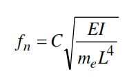
where U = streamwise flow velocity; D = outer diameter of pipe; me = effective mass (including structural mass, mass of content and added mass); fn = natural frequency of the pipe free span.
Natural frequency of free span pipe defined as:
post8-3

In practice, the use of these formula for estimation of maximum free span length is not very applicable since there is difficulties in determining the exact seabed conditions.Therefore, different approaches usually adopted. One of the method is modal analysis.
Modal Analysis
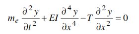
Natural frequency of pipelines can be obtained using the Euler-Bernoulli beam equation which is defined as (Xu et al, 1999 and Bai, 2000):
post8-5

with y = in-line displacement of pipe; x = position along the pipe span; t = time; C = total damping ratio; T = axial force of pipe (positive under tension); and F(t,u,y) = total external forces.
External forces and damping ratio only influence the resonance amplitude, so it can be ignored and the pipe free vibration equation is expressed in the following equation:
post8-6

There are several codes that can be used as reference containing free spanning on offshore pipeline, like DnV RP F105 (Pipeline Free Spanning) and API RP 11 11, 1999.

PREVENTION
In order to prevent crack due to free spanning, supports can be made to reduce the stress on the free span area. These supports include sand-filling or mini structure. A mini structure is shown in figure below:
post8-8

Bakhtiary, Abbas Yeganeh et al. Analysis of Offshore Pipeline Allowable Free Span Length. Iran University of Science and Technology. Iran. 2007.

Pipeline Welding Technology

The installation of gas pipe through the designated wetland areas of Mississippi and Alabama could prove challenging for any contractor, but the thick-walled pipe specified on the Gulfstream Project presented new welding challenges for contractor Sunland Construction Inc. Because the pipe is two times as thick as that typically used, Sunland relies on innovative welding techniques to decrease the number of weld passes necessary and most importantly, to assure the welds produced are consistent, x-ray quality.

Sunland Construction Inc., headquartered in Eunice, Louisiana, turned to The Lincoln Electric Company's Autoweld® automatic orbital pipe welding system for the fill and cap passes and the STT® (Surface Tension Transfer®) process to lay the critical root pass. By implementing these new welding technologies, Sunland has been able to remove one electrode pass from the root pass process as well as eliminate all grinding from this step. With the Autoweld system, the company has reduced the time to put in the fill and cap passes.

"We have realized dramatic improvements since using the new Lincoln welding systems in both higher quality and time savings," said Joe Ratcliff, Project Manager for Sunland Construction Inc. "Our welders are proud of the new equipment, it has made the welding portion of this job run smoothly."

Gulfstream Project

The Gulfstream Project is a natural gas pipeline that originates near Pascagoula, Mississippi and crosses the Gulf of Mexico to Manatee County, Florida. Once onshore, the pipeline stretches across south and central Florida to Palm Beach County. This natural gas pipeline will serve Florida utilities and power generation facilities, generating 1.1 billion cubic feet per day of additional natural gas - enough to supply electricity for 4.5 million homes.

Sunland Construction Inc.'s portion of the pipeline includes installation of 6.1 miles of 36" diameter pipe in Jackson County, Mississippi and 9 miles in Mobile County, Alabama.

A 27-year-old company with five divisions, Sunland won the Gulfstream job through a competitive bid process. More than 250 employees are being utilized on this project - taking a total of seven months to complete. Sunland expects its portion of the Gulfstream project to be wrapped up in early 2002.

According to Ratcliff, preparing for pipe installation on this job is no small feat. "Before we can even begin to weld, we must first clear the land, prepare a right of way, install piling in some areas, erect construction bridges and bring in additional soil where need. Because of the conditions of the wetland areas, all welding crews have to work on large, 4 ft. x 20-ft. timber mats. These mats, sometimes put down in a number of layers, provide a stable, dry work surface. Once work is complete in an area, Sunland Construction Inc. is also responsible for restoring the surrounding area to its original condition.

"Welding for this job is completed with three crews, one welding right after the other," noted Ratcliff. "The first crew installs the root pass, the second crew immediately follows using stick welding to accomplish a hot filler pass, and then the Autoweld crew completes the welding process with fill and cap passes."

Because of the extreme conditions on the site, the Autoweld process is performed inside of a welding "house" or modular unit that is lifted and moved every 40 ft. (from joint to joint) by a Caterpillar Challenger with a side boom.


The Pipe

Pipe for the on-land portion of the Gulfstream Project is provided by Berg Steel Pipe Corporation of Panama City, Florida and its parent company, Europipe GmbH of Germany. The X70 pipe ranges in wall thickness from 0.635 to 1.22. This thick-walled pipe was specified so the pipeline could handle the pressure range of the Gulfstream system. Pipe is coated with a Fusion Bond Epoxy (FBE) on both the interior and exterior, and a majority of the pipe is also concrete coated for buoyancy control.

Root Pass

Sunland Construction Inc. utilized the STT process because of the advantages it offered.

STT is a modified MIG process that uses high frequency inverter technology with advanced Waveform Control to produce high quality welds while also significantly reducing spatter and smoke. STT technology has the ability to control weld puddle heat independently of wire feed speed - this allows the welder more control over the puddle and provides the ability to adjust the heat input to achieve the desired root bead profile. The welder simply positions the arc on the forward portion of the weld puddle and follows it around the pipe in a vertical down fashion.

With the system, Sunland welders can achieve a uniform gap by using an internal, pneumatic clamp to line up and space the pipe for accurate welding.

For the Gulfstream Project in particular, STT is able to produce a quality weld and allows an increased amount of weld metal to be placed on the heavy wall pipe for improved resistance to cracking. With STT, Sunland only has to make one pass for the root bead as compared to two passes plus grinding time with stick.

"Since the root pass is the foundation for the rest of the weld, achieving a high quality, strong and uniform weld is very important to us," said Ratcliff. "We are very pleased with the STT. It has allowed us to save time and is an easy system for our welders to learn. The STT process is very forgiving, meaning that it helps compensate for misalignments, if and when necessary."

The two STT machines on the Gulfstream job site are used in conjunction with Lincoln's .045 L-56™ SuperArc® wire and 100 percent CO2 shielding gas. As compared to blended gases, CO2 is able to provide better penetration and is less expensive.

"The STT is able to apply a root bead with great consistency over a wide variety of joint conditions" explained Ratcliff.

Hot Filler Pass

Once the root pass is complete, the next team of welders follows closely behind to weld in the hot filler pass. Due to the thickness of the pipe on this job, Sunland Construction Inc. elected to put a single downhill hot filler pass over the root with a downhill, low hydrogen stick process. "The added filler metal we deposited at this stage gives us additional backing to lay the first wire filler and means that we don't have to make quite as many passes with the Autoweld system," noted Ratcliff.

To do this interim step, Sunland is using Lincoln's LH-D 80 rod with a conventional 300-amp Lincoln belt-driven welder.

Fill and Cap

For the Gulfstream Project, Sunland Construction Inc. decided to invest in an automated process to weld the fill and cap passes. Previously, Sunland has been completing the fill and cap passes with a 70+ stick electrode, welded vertical down and requiring numerous passes.

"We wanted an automatic method to increase efficiencies and decrease overall costs," said Ratcliff. "It was also important for us to find a system that could provide a quality product but yet was easy to operate.

In its quest, the company contacted a number of manufacturers to research which system would work best in this application. "We narrowed down our choices and visited a couple of manufacturers to try out their systems, one of those being Lincoln Electric," noted Ratcliff. "Our team traveled to Lincoln's Cleveland headquarters where we had the opportunity to run our procedures on an actual Autoweld set-up. After we returned, we listed the pros and cons of every system and Lincoln's Autoweld came out on top. A big factor in our decision was the amount of technical support that Lincoln could provide to us."


The Autoweld system is enclosed in a house, so that welding can be done out of the elements. These houses are moved by sidebooms ( Challengers ) from one length of pipe to the next. Sunland uses six Caterpillar Challengers with PTO driven generators to produce the 100 amps at 460 volts needed to operate the Autoweld and accessories.

Lincoln's Autoweld system uses a specially designed lightweight-welding head to travel around the circumference of the pipe. In addition, the unit utilizes an external crawler band placed on the pipe to one side of the field joint weld bevel. Two machines operating simultaneously complete the vertical up welding - one machine starts at the bottom with the other starts on the side. Once the machine that started on the side reaches the top, it then is positioned to start at the bottom to complete its side of the pipe. Using the vertical up process is a break from the traditional, vertical down welding typically utilized for pipe.

Each wall thickness of pipe requires different machine settings for each specific pass. These settings are charted and can easily be set from the machine. The Autoweld system uses a flux core .052" wire and a shielding gas of 25 CO2/75 argon.

With Autoweld, Sunland Construction Inc. is achieving repetitiously consistent, x-ray quality welds. "Autoweld makes a very consistent, uniform, and precision-controlled metal deposit," noted Ratcliff. "The weld has high tensile strength and good Charpy values in the weld and pipe heat zones. The machine is also very durable and dependable."

Sunland's Autoweld system is powered by an Invertec® V350-PRO, an extremely lightweight inverter that is able to handle multi-process applications. The hallmark of this power source is an extremely smooth arc due to the unit's advanced inverter technology.

"We feel the V-350 is the state of art in welding equipment, it gives you the ability to maintain precise settings and arc performance," claimed Ratcliff. "Even after long hours of use on our construction site, the machine was dependable."

Quality Control

All welds once completed are visually inspected and then x-rayed with an internal crawler. All welds must meet API 1104 Section 9 requirements.

Service

Sunland Construction Inc. has been extremely pleased with the service it receives from Lincoln. "The on site support provided by the Lincoln Electric Mobile team of Troy Gurkin and Steven Brown has been superb," said Ratcliff. "We also enjoyed tremendous support from the Cleveland based Autoweld group including Eric Stewart, Autoweld technician, who was on site for much of the project. Lincoln has gone out of its way to help us implement our new processes and suggest new technologies when appropriate."

Sunland has also taken advantage of Lincoln's training programs on-site and in Cleveland. "Lincoln was challenged with taking welders at all different levels of expertise and work with them to learn to understand and operate the Autoweld system. It was a massive training effort that required quite a bit of Lincoln's time. We appreciate all they have done to make this job run smoothly."

Future

The new STT and Autoweld machines can be used on future jobs to increase efficiencies.

Pipeline Construction

Pipeline construction is divided into three phases, each with its own activities: pre-construction, construction and post-construction.


Pre-Construction

Surveying and staking

Once the pipeline route is finalized crews survey and stake the right-of-way and temporary workspace. Not only will the right-of-way contain the pipeline, it is also where all construction activities occur.

Preparing the right-of-way

The clearly marked right of way is cleared of trees and brush and the top soil is removed and stockpiled for future reclamation. The right-of-way is then leveled and graded to provide access for construction equipment.

Digging the trench

Once the right-of-way is prepared, a trench is dug and the centre line of the trench is surveyed and re-staked. The equipment used to dig the trench varies depending on the type of soil.

Stringing the pipe

Individual lengths of pipe are brought in from stock pile sites and laid out end-to-end along the right-of-way.

Construction

Bending and joining the pipe

Individual joints of pipe are bent to fit the terrain using  a hydraulic bending machine. Welders join the pipes together using either manual or automated welding technologies. Welding shacks are placed over the joint to prevent the wind from affecting the weld. The welds are then inspected and certified by X-ray or ultrasonic methods.

Coating the pipeline

Coating both inside and outside the pipeline are necessary to prevent it from corroding either from ground water or the product carried in the pipeline. The composition of the internal coating varies with the nature of the product to be transported. The pipes arrive at the construction site pre-coated, however the welded joints must be coated at the site.

Positioning the pipeline

The welded pipeline is lowered into the trench using bulldozers with special cranes called sidebooms.

Installing valves and fittings

Valves and other fittings are installed after the pipeline is in the trench. The valves are used once the line is operational to shut off or isolate part of the pipeline.

Backfilling the trench

Once the pipeline is in place in the trench the topsoil is replaced in the sequence in which it was removed and the land is re-contoured and re-seeded for restoration.

Post Construction

Pressure Testing

The pipeline is pressure tested for a minimum of eight hours using nitrogen, air, water or a mixture of water and methanol.

Final clean-up

The final step is to reclaim the pipeline right-of-way and remove any temporary facilities.

Pipeline Decommissioning


Decommissioning Regulations for Pipelines

Although a number of international treaties govern the disposal of waste at sea, including the management of decommissioned offshore structures, there are no international regulations or guidelines, relating specifically to the decommissioning of pipelines. At present, pipeline decommissioning is covered within national legislation.

In the UK, the Petroleum Act 1998 [Ref 3] outlines the requirements for owners of installations and pipelines
to obtain approval for their decommissioning programme from the Secretary of State. The decommissioning programme should contain details of cost and proposals for removal and disposal. It must be supported by an EIA and is submitted to the Department for Energy and Climate Change (DECC).

Pipelines should be the subject of a separate decommissioning programme unless they are located within the same field as other equipment or installations to be decommissioned at the same time.

In addition to the approval of the decommissioning programme for a pipeline, the following may also be required:

• Confirmation that the requirements of the Coast Protection Act 1949 Section 34 Part II have been satisfied

• Fulfilment of notification requirements for the Health and Safety Executive (HSE) under regulation 22 of the Pipeline Safety Regulations 1996 [Ref 7]

• Any environmental consents or permits required during decommissioning activity

• Disposal of materials on shore must comply with relevant health and safety, pollution prevention and waste requirements/permits

If part or the entire pipeline is to be removed or the decommissioning programme would result in a change to 
any part of the Table A information in the original Pipeline Works Authorisation (PWA) then a PWA Variation would also be required.

If the approved decommissioning programme for a pipeline contains proposals for the placement of associated materials on the seabed such as rock dump, then a licence must be obtained under the Marine and Coastal Access Act 2009 [Ref 4] in England and Wales or the Marine (Scotland) Act 2010.

In Norway, pipelines and cables are not specifically referred to in Chapter 5 Decommissioning, of the Petroleum Act 1996. They are, however, covered by a separate White Paper 47 (1999–2000), ‘Disposal of Pipelines and Cables on the Norwegian Continental Shelf’.


Notification of Disused Pipelines


In the UK, the owner of a pipeline must notify the DECC when a pipeline reaches the end of its operational life. Under certain circumstances, this may be before other facilities in the same field. In such cases the DECC may consider the deferral of decommissioning for the pipeline until the end of the whole field life.

Some pipelines may represent important UKCS infrastructure and provide the means for future development of hydrocarbons reserves, or storage of carbon dioxide or gas in the basin. To allow for the future reuse, the decommissioning of such pipelines may also be deferred. 

The deferral of pipeline decommissioning to the end of field life or for possible reuse is carried out under the ‘Interim Pipeline Regime’ (IPR). The DECC will send the pipeline owner a Disused Pipeline Notification form requesting details on the status of the pipeline. The DECC will consult with other government departments and then issue a letter outlining the conditions under which it is prepared to defer decommissioning to a specified date. If reuse of the pipeline is considered viable, then suitable and sufficient maintenance of the pipeline is required of the owner.

Flexible Pipe


In the advanced development of technology, oil and gas industry explores further from shore and deeper to the basin. It is inevitable that the deeper it goes, more pressure it receives. This become a concern in planning a safe pipeline system. For that reason, a new kind of offshore pipeline is invented, the flexible pipe.
A flexible pipe is made up of several different layers. The main components are leak-proof thermoplastic barrier and corrosion-resistant steel wires. The helically steel wires give the structure its high pressure-resistant and excellent bending characteristic, so it provides flexibility.
Image
A figure of typical flexible pipe.


MAIN COMPONENTS

Figure below identifies the main components of flexible pipe cross section:
Image
  1. Interlocked stainless steel carcass
  2. Internal pressure sheath, made from nylon, poly vinylidene flouride (PVDF) and high density polyethylene (HDPE)
  3. Zeta spiral (pressure armour), made from rolled carbon steel
  4. Tensile armour (double cross wound armours), made from flat rectangular wires
  5. Outer thermoplastic sheath, made from non-metallic materials

MAIN CHARACTERISTICS

  • Flexible. Makes it possible to spool the pipe on a reel or in a carousel for efficient and quick transportation and installation.
  • Easy to install. Since the flexible pipe is in continuous form, laying speed will be much faster than laying ordinary rigid carbon steel pipeline.
  • Modularity. The independent layers of a flexible structure enable it to be tailored to the precise needs of a specific development.
  • Corrosion resistant. Since the steel wires are not in direct contact with the conveyed fluid, they do not require the same corrosion resistance as steel pipe.
  • High pressure resistant. Flexible pipes resist all fluid pressures encountered in the most complex subsea application. Besides, the modularity of the flexible pipe manufacturing process enables to adjust pipe thickness, shape, and number of steel wire layers to satisfy a specific requirement.
Image
The image above shows the physical form of flexible pipe.
Sources :