Tuesday, February 16, 2016

Hydrotest on Offshore Pipeline

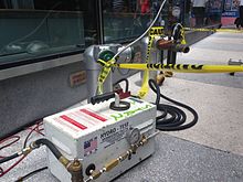
A hydrostatic test is a way in which pressure vessels such as pipelines, plumbing, gas cylinders, boilers and fuel tanks can be tested for strength and leaks. The test involves filling the vessel or pipe system with a liquid, usually water, which may be dyed to aid in visual leak detection, and pressurization of the vessel to the specified test pressure. Pressure tightness can be tested by shutting off the supply valve and observing whether there is a pressure loss. The location of a leak can be visually identified more easily if the water contains a colorant. Strength is usually tested by measuring permanent deformation of the container. Hydrostatic testing is the most common method employed for testing pipes and pressure vessels. Using this test helps maintain safety standards and durability of a vessel over time. Newly manufactured pieces are initially qualified using the hydrostatic test. They are then re-qualified at regular intervals using the proof pressure test which is also called the modified hydrostatic test. Testing of pressure vessels for transport and storage of gases is very important because such containers can explode if they fail under pressure.
Hydrotesting of pipes, pipelines and vessels is performed to expose defective materials that have missed prior detection, ensure that any remaining defects are insignificant enough to allow operation at design pressures, expose possible leaks and serve as a final validation of the integrity of the constructed system. ASME B31.3 requires this testing to ensure tightness and strength.
Buried high pressure oil and gas pipelines are tested for strength by pressurizing them to at least 125% of their maximum allowable working pressure (MAWP) at any point along their length. Since many long distance transmission pipelines are designed to have a steel hoop stress of 80% of specified minimum yield strength (SMYS) at maximum allowable operating pressure (MAOP), this means that the steel is stressed to SMYS and above during the testing, and test sections must be selected to ensure that excessive plastic deformation does not occur.
Test pressures need not exceed a value that would produce a stress higher than yield stress at test temperature. ASME B31.3 section 345.4.2 (c)
Other codes require a more onerous approach. BS PD 8010-2 requires testing to 150% of the design pressure – which should not be less than the MAOP plus surge and other incidental effects that will occur during normal operation.
Leak testing is performed by balancing changes in the measured pressure in the test section against the theoretical pressure changes calculated from changes in the measured temperature of the test section.
Australian standard AS2885.5 “Pipelines—Gas and liquid petroleum: Part 5: Field pressure testing” gives an excellent explanation of the factors involved.
ASME B 31.8 specifies the test pressure factors for pipelines operating at hoop stress of 30% of SMYS. This code also limits the maximum hoop stress permitted during tests for various class locations if the test medium is air or gas. There are different factors associated with different pipeline class and division locations. For example, the hydrotest pressure for a class 3 or 4 location is 1.4 times the MOP. The magnitude of test pressure for class 1 division 1 gas pipeline transportation is usually limited to 125% of the design pressure, if the design pressure is known. The allowed stress in the pipe material is limited to 72% of SMYS. In some cases it is extended to 80% of SMYS. The position of Pipeline and Hazardous Material Safety Administration (PHMSA) is similar. Thus, a pipeline designed to operate continuously at 1,000 psig will be hydrostatically tested to a minimum pressure of 1,250 psig.
Sources :

Pipeline Mechanical Connector (Flange)

Various method exist for joining ends of subsea pipelines. These methods include the following:
  • Flanged connection
  • Atmospheric welding
  • Hyperbaric Welding
  • Mechanical Connectors
Flanges are pre-installed on each pipe end during laying. The pipe ends are positioned approximately in line with the flanges 50-200 ft apart. An adjustable fixture (template) is lowered to the seabed and temporary attached to the flanges. The fixture is locked in position, released, and raised to the surface. A rigid pipe spool is prepared to match the exact dimensions of the fixture, lowered to the seabed, and bolted into place.
                                            Flange Connection
A swivel-ring flange is used on one spool end to facilitate alignment of the bolt holes in the flanges. This method is generally limited to applications involving relatively small diameters and shallow water, although flanges have been used to at least 36-in diameter and in 500-ft water depths in the North Sea.

Flanges are low in cost, but they can take a long time to install and may leak during pressure testing. A leaking flange can be difficult to diagnose. In one installation, it took 2 weeks to locate the source of a small leak during a hydrotest, which was due to a leaking flange. However, flanges are considered trouble-free once they have been installed and tested. Flanges are sometimes used at the foot of risers to facilitate replacement of a riser.

The process of tightening large flanges has been made considerably easier and faster by the use of a hydraulic bolt-tensioning tool. The Hydra-Tight tool, sold in the U.S. by Flexatalic Gasket Co., has been used in the North Sea for several years. It consists of a series of hydraulically operated tensioners which are attached to protruding ends of the flange studs. Hydraulic power provided from the surface causes the tensioners to tension each stud uniformly. The nuts may then be tightened in as little as 3 hr using the Hydra-Tight tool. The primary advantage, however, is uniform tensioning of the studs. This reduces the likelihood of a leak, especially for large flanges.

A variation of the flanged spool that is gaining wider acceptance is the use of a ball flange to accommodate angular misalignment. Small diameter lines (10-12 in. or less) in 200-300 ft of water may often be lifted to the surface to make a connection using a ball connector. The pipe is dewatered, if necessary, and one end is raised by one or more lifting points. A ball-connector half is welded to this first pipe end. A joint or two of pipe are first welded on to bridge any gap between the two pipe ends.

The first pipe end is lowered to the seabed so that it overlaps the second pipe end. A measurement is taken on bottom, and the second pipe end is raised to the surface. The pipe is cut, the second ball half is pipe end is welded on the pipe, and the pipe is lowered to the seabed. The two pipe ends are then lifted slightly and the ball halves are mated. The connected pipe is lowered to the seabed and the bolts are tightened to lock and seal the ball joint.

If the pipes must be dewatered for lifting, temporary end caps are attached to the ball halves before the pipe ends are lowered. After the pipes are flooded, the temporary caps are removed.

The ball connectors may also be used in pairs at the ends of a rigid spool for new construction or for a long spool repair when pipe ends can be lifted to the surface. Measurement of the required spool length must be accurately made since the ball connectors will provide only limited length adjustment. Moreover, an axial movement of about one pipe diameter is needed to mate the halves of a ball joint.
                                                                     Gas Pipeline Flange
Source : Mouselli, A. H. Offshore Pipeline Design, Analysis, and Methods. USA: PennWell Books. 1981.

HDPE Pipe

High-density polyethylene (HDPE) or polyethylene high-density (PEHD) is a polyethylene thermoplastic made from petroleum. It is sometimes called "alkathene" or "polythene" when used for pipes. With a high strength-to-density ratio, HDPE is used in the production of plastic bottles, corrosion-resistant piping, geomembranes, and plastic lumber. HDPE is commonly recycled, and has the number "2" as its resin identification code (formerly known as recycling symbol). In 2007, the global HDPE market reached a volume of more than 30 million tons.
HDPE is known for its large strength-to-density ratio. The density of HDPE can range from 0.93 to 0.97 g/cm3 or 970 kg/m3. Although the density of HDPE is only marginally higher than that of low-density polyethylene, HDPE has little branching, giving it stronger intermolecular forces and tensile strength than LDPE. The difference in strength exceeds the difference in density, giving HDPE a higher specific strength. It is also harder and more opaque and can withstand somewhat higher temperatures (120 °C/ 248 °F for short periods, 110 °C /230 °F continuously). High-density polyethylene, unlike polypropylene, cannot withstand normally required autoclaving conditions. The lack of branching is ensured by an appropriate choice of catalyst (e.g., Ziegler-Natta catalysts) and reaction conditions.


High density polyethylene plastic pipe (HDPE) delivers exceptional value, unwavering reliability and remarkable advantages over conventional types of piping. It's today's right choice for water, drainage, fuel gas, conduit and plumbing & heating. Other reasons HDPE is a superior choice:

  • Long-term service life
  • Highly-resistant to corrosion, abrasion and chemicals
  • Strong, durable, flexible and lightweight
  • Longer-length pipe with leak-proof joints
  • Lower labor requirements for installations
  • Significant overall cost savings

Sources : https://en.wikipedia.org/wiki/High-density_polyethylene

http://www.jayaterusmultiniaga.com/product/high_density_polyethylene_hdpe_pipes__fittings.html

Pipeline Thermal Insulation

Assets such as offshore pipelines, risers, spools and subsea structures which transport liquid products may be required to maintain a minimum temperature while the product is being transported within the asset, particularly offshore. Some liquids such as oil and gas can leave wax or hydrate deposits if a minimum temperature is not maintained. These deposits can, over time, build up and block the asset/pipeline either reducing or completely stopping flow/production. External wet insulation can be designed and applied to ensure the reduction in product temperature is kept within a range so the risk of deposits during production is acceptable. Insulation can also reduce the frequency of pigging operations during the life of the asset.

During other operational events, such as pipeline shutdowns, the product is contained in a stationary state within the asset/pipeline while the process facility has other operations performed. Similarly, to avoid deposits during these shutdown periods external insulation can be designed and applied to ensure the reduction in product temperature is kept within a range so the risk of deposits during shutdowns is acceptable.

Injected Molded Polyurethane Applications provide thermal insulation and are commonly used offshore on flowline and riser field joints, spools and subsea structures. It is used less often onshore to thermally insulate pipelines and spools. The asset will require to have been pre-coated with an anti-corrosion layer prior to the thermal insulation application.

The preparation for IMPU requires that the anti-corrosion layer is in good condition and the bevel faces of the parent coating (usually PP) are cleaned, abraded and then pre-heated to build bond strength between the PP and IMPU. Once this preparation is completed a mold is placed over the area to be treated and Solid Polyurethane is injected into the annulus and often overlapping the parent coating bevel faces and onto the OD surface of the PP. Once the material cures the mold is removed and inspected.

OJS can apply all Solid Polyurethanes available on the market however we recommend our own formulated solid polyurethane material calledDensiflex for IMPU coatings. Densiflex is mercury free and fast curing – which is suitable for the offshore market.

Injected Molded Polypropylene Applications provide thermal insulation on pipeline and riser field joints and spools. The asset will require to have been pre-coated with an anti-corrosion layer prior to this thermal insulation application.

The preparation for IMPP requires that the anti-corrosion layer is in good condition and the bevel faces of the parent coating (usually PP) are cleaned, abraded and then pre-heated to build bond strength between the PP and IMPP. Once this preparation is completed a mold is placed over the area to be treated and Solid Polypropylene is injected into the annulus. Once the material cures the mold is removed and inspected.
Contoh Pipeline Thermal Insulation

Spiral Pipe for Offshore Application

Spiral welded line pipe has been used extensively for onshore applications, however there has been some reluctance to specify spiral welded line pipe for offshore applications. A joint industry project is beeing carried out together with coil manufacturers, pipe manufacturers, installation contractors and operators to review the status regarding offshore applications for spiral welded pipes and identify the most critical technology gaps using a technology qualification process. Detailed suggestions as to how the gaps can be met have been made. An update on efforts to close these gaps is ongoing.

The challenges for spiral welded line pipe include design, metallurgical and quality control issues. The design issues include fracture arrest, collapse and displacement controlled loading conditions which are all highlighted in DNV standard for submarine pipelines (DNV OS F101). The design issues regarding load controlled displacement are mainly due to limited experience with spiral welded line pipe subjected to large strains. For running fracture the limited experience with spiral welded pipe for offshore applications is an issue.

There are 5 new spiral welded pipe mills in United States so availability has improved. The review includes an assessment of typical pipe material test results and whether properties required for offshore applications can reasonably be expected.

It appears that the industry has a general understanding that the performance of spiral welded (SAWH) pipes is different to Submerge Arc Welded (SAWL)/ High Frequency Welded (HFI)/ Electric Resistance Welded ERW linepipe when exposed to the same loading conditions, and that currently existing design standards for offshore applications may not be applicable. An important issue is to establish how the spiral wound linepipe can be produced consistently to a high level of quality, and what is required by the design standard for spiral welded pipe to be fit for purpose for offshore use. Some of the main areas of concern regarding the quality of spiral wound linepipe will be discussed. The aim is to assess whether SAWH linepipe can be considered equivalent to SAWL and HFI/ERW linepipe.

The use of spiral welded linepipe (SAWH) for pipelines has generally been themost popular manufacturing choice of linepipe for onshore low pressure pipelines, pipelines transporting water, ship borne piping, or very shallow water, low pressure pipelines (≤ 500 ft).

Recently there has been more interest in the use of spiral wound linepipe, dueto the following reasons:
• There are five new SAWH pipe mills in America with “state-of-the-art” technology.
•  SAWH linepipe is a cost-effective solution compared to the other manufacturing processes.
•  Generally, the chemical compositions, mechanical properties anddimensional tolerances are assumed to be comparable to SAWL pipe.
•  SAWH linepipe can be manufactured in 80 ft lengths with diameters from 20 to more than 100-inch OD and wall thicknesses ranging from approximately 9to 25 mm.
•  Some SAWH pipe mills have coating capabilities for 80 ft pipe lengths(FBE and 3-layer coating systems). 80 ft pipe lengths could mean less fabrication costs for the installation contractors.

Pipeline Stress Analysis

WHAT IS STRESS ANALYSIS?
Piping stress analysis is a term applied to calculations, which address the static and dynamic loading resulting from the effects of gravity, temperature changes, internal and external pressures, changes in fluid flow rate and seismic activity. Codes and standards establish the minimum requirements of stress analysis.

PURPOSE OF PIPING STRESS ANALYSIS
Purpose of piping stress analysis is to ensure:
·         Safety of piping and piping components.
·         Safety of connected equipment and supporting structure.
·         Piping deflections are within the limits.

HOW PIPING AND COMPONENTS FAIL (MODES OF FAILURES)
There are various failure modes, which could affect a piping system. The piping engineers can provide protection against some of these failure modes by performing stress analysis according to piping codes.

1.  FAILURE BY GENERAL YIELDING : Failure is due to excessive plastic deformation.
·         Yielding at Sub Elevated temperature: Body undergoes plastic deformation under slip action of grains.
·         Yielding at Elevated temperature : After slippage, material re-crystallizes and hence yielding continues without increasing load. This phenomenon is known as creep.

2. FAILURE BY FRACTURE : Body fails without undergoing yielding.
·         Brittle fracture : Occurs in brittle materials.
·         Fatigue: Due to cyclic loading initially a small crack is developed which grows after each cycle and results in sudden failure

WHEN PIPING AND COMPONENTS FAIL (THEORIES OF FAILURE)
Various theories of failure have been proposed, their purpose being to establish the point at which failure will occur under any type of combined loading. The failure theories most commonly used in describing the strength of piping systems are

·         Maximum principal stress theory
This theory states that yielding in a piping component occurs when the magnitude of any of the three mutually perpendicular principle stresses exceeds the yield point strength of the material.

·         Maximum shear stress theory
This theory states that failure of a piping component occurs when the maximum shear stress exceeds the shear stress at the yield point in a tensile test.
In the tensile test, at yield, S1 =Sy (yield stress), S2=S3=0.So yielding in the components occurs when
Maximum Shear stress =τmax=S1-S2/ 2=Sy / 2
The maximum principal stress theory forms the basis for piping systems governed by ASME B31.3.
Note: maximum or minimum normal stress is called principal stress.

Pipeline Ending Manifold (PLEM)

Subsea manifold is a flow-routing subsea hardware (subsea flow router) that connects between subsea trees and flowlines. It is used to optimize the subsea layout arrangement and reduce the quantity of risers connected to the platform. If connected to dual flowlines, the manifold can typically accommodate pigging and have the capability of routing production from a particular tree to a particular flowline.
Pipeline End Manifold (PLEM)
It a simpler version of a cluster manifold generally designed to direct fluids for only one or two subsea Christmas trees. A PLEM generally connects directly to a subsea flow line without the use of a pipeline end termination (PLET).
Manifold Compenents 
A manifold is typically composed of the following major components:
  • Pipework and valves – contains and controls the production and injection fluids.
  • Structure framework – protects and supports the pipework and valves.
  • Subsea connection equipment – allows subsea tie-in of multiple pieces of equipment. Types include vertical, horizontal and stab-and-hinge-over connections.
  • Foundation – interface between the manifold structure and seabed.
  • Controls Equipment – allows the remote control of any hydraulically actuated subsea manifold valves and the monitoring of production and injection fluids. Control pods may be either internal or external to the manifold.
Valves
Valves on the manifold are essential for directing and controlling the flows. They can be either manual or hydraulically actuated. Sometimes chemical injection valves are placed on the manifold as well.
  • Branch valves are generally slab type gate valves (similar to tree valves). Their sizes are based on the production/injection tree size.
  • Flowline header valves are also gate type, but ball valves have been used previously. Their sizes are based on the flowline size.
  • Materials are chosen for compatibility with production and injection fluids. Most of time, it is CRA-clad.
  • Double barrier philosophy generally used against production fluids.
    -Two valves in series
    -One valve and one pressure cap
    -Primary seal is generally a metal-to-metal seal
Pipework
A wide range of pipework configurations is possible. Each header connects to an individual flowline. the pipework sizing is based on the tree piping size and the flowline diameters. The main circuit is designed to accommodate pigging operations. The material of construction needs to be compatible with production and injection fluids.
  • Test headers can be incorporated to test individual or groups of trees
  • Test headers can be a second or even third header isolated in the manifold
  • Insulation may be required for unscheduled or emergency shutdowns
Control System
Control system for the manifolds is the same as the control system for the trees. Multiple options for the control system have been used in the manifold design
  • No controls on the manifold. The manifold is controlled by tree subsea control modules (SCMs).
  • SCMs on the manifold.
  • Manifold with control system distribution units with flying leads going to trees.
Framework Structure
The framework is a welded structure to provide support for the pipework and valves and contain the foundation interface structure. The pipework is allowed to float inside the framework within limits and it is not rigidly attached to the frame. The frame can also be used for lifting and landing of the jumper tie-in tools.
Foundation
  • Mud mats – a simple foundation resting directly on the seabed, generally with a short skirt around the perimeter to resist lateral loads.
  • Piles – long cylindrical structures embedded into the soil intended to hold a subsea structure above the seabed. Foundations may utilize one or more individual piles.
  • Intermediate Structures – an intermediate structure can be used to interface a subsea manifold with a pile foundation to reduce weight of the manifold structure or to ease retrieval of the manifold. Intermediate structures can be either retrievable or permanent structures.
Tie-ins to wells and flowlines
The tie-in hubs placed on the outer edge of the manifold, which are used to tie-in jumpers that bring in fluid from the production wells and export fluid into the flowlines (production manifold). The tie-in sizing is based on the tree piping size and the flowline diameters. and the loads applied from the flowlines
Insulations
Generally gas manifolds are not insulated and oil manifolds are insulated. For oil production, insulation is necessary to allow adequate cool-down time to treat or remove trapped production water. Gas production is generally treated continuously with chemicals to prevent hydrates.
Deployment method
The following vessels are typically used for manifold deployment:
  • Drill Rig: through moon pool or keel-hauled on drill string
  • Heavy Lift vessels (Derrick Barges): through moon pool or over side
  • Work-class vessels: over side on crane or winch
The following equipments are typically required:
  • Manifold hydraulic installation tool
  • Sling sets, either wire rope or synthetic fiber
Applicable API Specs
  • API Spec 17P – Templates and Manifolds
  • API Spec 17D – Specifications for subsea wellhead and Christmas tree equipments
  • API Spec 17A – Recommended practice for design and operation of subsea production systems
  • API Spec 17H, ISO 13628-8 – ROV Interfaces